This article provides information, illustrations and detalied exmaples to assist in planning for the installation of a large industrial generator set at your facility or worksite. We pick up and continue to expand on the previous Site Planning for an Industrial Generator Installation article.

In this article, additional tips for site preparation and project management are included as well as details on fuel systems and some initial electrical connection considerations.
The three generator applications covered are:
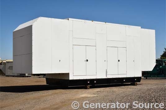
• Permanente Enclosed Generator – Outdoor installation of a canopy generator system installation to include, setting and connecting generator and auxiliary fuel system
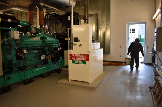
• Generator Located Inside Factory – Indoor installation of a generator system on a skid. Installation to include setting generator and connection of auxiliary systems.
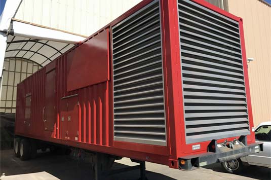
• Portable enclosed generator – Basic inspection/setup and power system installation diagrams.
Permanente Enclosed Generator
A Caterpillar 1500 kW generator set enclosed in a canopy is chosen for installation. The generator is equipped with a 1000 gallon double walled fuel tank
Setting Generator
A reinforced concrete pad with generator mounting studs has been installed and the concrete has had appropriate time to set. Generator set has been unloaded and is ready to set on concrete pad
WARNING
This generator set requires a crane to move. To reduce the possibility of personal injury, always use the lifting equipment that has proper capacity. Be sure to have assistance when needed to align generator set.
It’s a common practice to unload and set the generator in the same day to save on crane costs. When setting the generator set the following factors should be considered:
• A lifting device that will allow the generator set to be safely lifted and placed at level on the concrete pad.
• A crane with capability of placing generator set on the concrete pad.
Possible sequence for setting generator set is:
1. Connect generator set to lifting device and crane.
2. Move and align generator set with concrete mounting studs.
3. Install attaching hardware (washer, lock washer, nut).
4. Fuel generator tanks.
5. Connect generator output to Automatic Transfer Switch (ATS).
Setting Auxiliary Fuel Tanks
A Caterpillar 1000 kW generator set uses fuel at the following rates:
• 22 GPH (Gallon per hour) at 25% load ÷ 1600 gallon = 72 hours operation.
• 71 GPH at 100% load ÷ 1600 gallon = 22 hours operation.
Auxiliary fuel tanks can extend the operation time during major power outages such as extreme foul weather, loss of electrical substations and availability of partial power. This facility will require a 600 gallon back up tank to maintain extended generator use and allow for fuel delivery in emergency situations.
The auxiliary fuel tank is set when the generator is set. During Site Planning phase of the project, concrete pad was installed with the studs for mounting fuel tank. Possible sequence for setting the auxiliary fuel tank is:
• Locate fuel tank, align with mounting studs, set and install washers and nuts.
• Install fuel pump and filter assembly onto tank.
• Install retractable hose reel and connect to fuel pump.
• Fuel auxiliary tank and all fluids.
• Connect fuel pump electrical supply to switchboard (supplied by generator in emergency conditions).
Generator Inside Factory
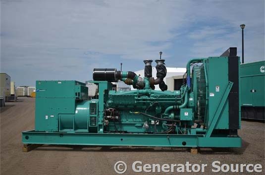
A Cummins 1250 kW generator set is selected for the facility. The generator systems (engine, cooling and generator) are placed on a skid as a complete unit. Generator set is a ready replacement for a generator that experienced catastrophic failure and was a complete loss.
Setting Generator
A Cummins 1250 kW generator weighs 25,000 lbs. The facility is equipped with a gantry to support removal and installation of large equipment. Contracting a local crane company to unload generator shifts the responsibility of off-loading and placing the set. Crane will connect to the generator and boom it into facility maintenance door. Maintenance personnel will connect gantry to generator set onto pad.
Connecting Auxiliary Systems
When the generator is set onto the pad it is common to use industrial rubber mounts. After the generator is secured into place the gantry is usually removed from the area. Indoor booms are available to connect heavy auxiliary equipment. Always check with local and federal regulations prior to connecting systems. Some of the auxiliary systems to be connected are:
• Exhaust systems – Mufflers and exhaust pipes must be properly insulated and routed to outside air. Exhaust from engine must meet EPA guidelines.
• Cooling air – Louvers controlled by generator control system are installed on the outside of the building. Ductwork is connected to generator radiator/aftercooler.
• Fuel system. – Fuel lines are connected from supply tank to engine fuel filter block. Fuel supply must be mounted on correct side of block for fuel flow through filters. The transfer pump (supplies fuel to filters) must be capable of supplying engine at full load.
• Electrical systems – Generator is and engine are completely electrically connected. Connect following systems:
- Control panel – Connected to automatic transfer switch (ATF) for start signal. When control panel receives signal it commands generator start and controls operation.
- Generator output – Connected to supply side of automatic transfer switch. When transfer switch closes current flows to switch board.
- Louvers – Connected to control panel. Can be opened partially or completely depending cooling system demand.
• Intake air – Room supply air system must be capable of supporting generator at full load.

Portable Enclosed Generator
Customer is a construction company with a contract for a major addition for a hospital. In the initial stages of construction one portable Baldor 2,000 kW generator set will be required. As the construction reaches final stages a second unit will be needed to support all required services until utilities are connected. Following steps reviewed:
• Inspecting Generator After Transport – Locating and pre-start/pre-load suggestions.
• Electrical Connection – Single and dual generator set ups.
Inspecting Generator After Transport
When the portable generator arrives on site, performing basic generator inspection can aid in preventing un-necessary shutdowns. These steps and inspections include:
• Generator Location – Generator is located in flat, stable area that allows enough room for second generator. Fuel trucks can access generator(s).
• Lifting Gear – Lifting gear is properly supported with dunnage. Generator is level.
• Fueling – Some states require empty fuel tanks. Fuel tanks as needed.
• Fluid Level – Check coolant and oil levels for engine.
• Start Engine and Inspect – Prior to connecting generator set to load, start engine at generator control panel and inspect for:
- Fuel leaks
- Coolant leaks
- Oil leaks
Electrical Connection Options
The configuration requirements for this project require a single generator set for initial stages and in final stages adding all equipment and a second generator to accommodate end of project requirements Always:
• Locate transfer switch in a clean dry area near critical load.
• Provide circuit breaker between generator and automatic transfer switch.
• Adhere to all Federal and Local requirements when designing system.
Single Generator
The disconnect switch supplies power to breaker panel. Generator set supplies power to the breaker panel. Breaker panel supplies panel to non-critical equipment and automatic transfer switch.
When critical power is lost, generator starts and automatic transfer switch moves to enable power to be supplied by generator set.
Dual Generator
Project has advanced to the need for a second generator. Two separate generators supplying two separate circuits are needed. This configuration can be considered as a parallel setup. The following describe this set up:
• Generator(s) supply routed through paralleling panel
• Expanded breaker panel to allow for two generators (illustrated as two separate panels).
• Use of two automatic transfer switches allows for separation of loads.

>>Back to Articles & Info<<