|
 Generators are useful appliances that supply electrical power during a power outage and prevent discontinuity of daily activities or disruption of business operations. Generators are available in different electrical and physical configurations for use in different applications. In the following sections, we will look at how a generator functions, the main components of a generator, and how a generator operates as a secondary source of electrical power in residential and industrial applications. Generators are useful appliances that supply electrical power during a power outage and prevent discontinuity of daily activities or disruption of business operations. Generators are available in different electrical and physical configurations for use in different applications. In the following sections, we will look at how a generator functions, the main components of a generator, and how a generator operates as a secondary source of electrical power in residential and industrial applications.
How does a generator work?
An electric generator is a device that converts mechanical energy obtained from an external source into electrical energy as the output.
It is important to understand that a generator does not actually ‘create’ electrical energy. Instead, it uses the mechanical energy supplied to it to force the movement of electric charges present in the wire of its windings through an external electric circuit. This flow of electric charges constitutes the output electric current supplied by the generator. This mechanism can be understood by considering the generator to be analogous to a water pump, which causes the flow of water but does not actually ‘create’ the water flowing through it.
The modern-day generator works on the principle of electromagnetic induction discovered by Michael Faraday in 1831-32. Faraday discovered that the above flow of electric charges could be induced by moving an electrical conductor, such as a wire that contains electric charges, in a magnetic field. This movement creates a voltage difference between the two ends of the wire or electrical conductor, which in turn causes the electric charges to flow, thus generating electric current.
Main components of a generator
The main components of an electric generator can be broadly classified as follows:
- Engine
- Alternator
- Fuel System
- Voltage Regulator
- Cooling and Exhaust Systems
- Lubrication System
- Battery Charger
- Control Panel
- Main Assembly / Frame
A description of the main components of a generator is given below.
Engine
The engine is the source of the input mechanical energy to the generator. The size of the engine is directly proportional to the maximum power output the generator can supply. There are several factors that you need to keep in mind while assessing the engine of your generator. The manufacturer of the engine should be consulted to obtain full engine operation specifications and maintenance schedules.
(a) Type of Fuel Used – Generator engines operate on a variety of fuels such as diesel, gasoline, propane (in liquefied or gaseous form), or natural gas. Smaller engines usually operate on gasoline while larger engines run on diesel, liquid propane, propane gas, or natural gas. Certain engines can also operate on a dual feed of both diesel and gas in a bi-fuel operation mode.
(b) Overhead Valve (OHV) Engines versus non-OHV Engines – OHV engines differ from other engines in that the intake and exhaust valves of the engine are located in the head of the engine’s cylinder as opposed to being mounted on the engine block. OHV engines have several advantages over other engines such as:
• Compact design
• Simpler operation mechanism
• Durability
• User-friendly in operations
• Low noise during operations
• Low emission levels
However, OHV-engines are also more expensive than other engines.
(c) Cast Iron Sleeve (CIS) in Engine Cylinder – The CIS is a lining in the cylinder of the engine. It reduces wear and tear, and ensures durability of the engine. Most OHV-engines are equipped with CIS but it is essential to check for this feature in the engine of a generator. The CIS is not an expensive feature but it plays an important role in engine durability especially if you need to use your generator often or for long durations.
Alternator
The alternator, also known as the ‘genhead’, is the part of the generator that produces the electrical output from the mechanical input supplied by the engine. It contains an assembly of stationary and moving parts encased in a housing. The components work together to cause relative movement between the magnetic and electric fields, which in turn generates electricity.
(a) Stator – This is the stationary component. It contains a set of electrical conductors wound in coils over an iron core.
(b) Rotor / Armature – This is the moving component that produces a rotating magnetic field in any one of the following three ways:
(i) By induction – These are known as brushless alternators and are usually used in large generators.
(ii) By permanent magnets – This is common in small alternator units.
(iii) By using an exciter – An exciter is a small source of direct current (DC) that energizes the rotor through an assembly of conducting slip rings and brushes.
The rotor generates a moving magnetic field around the stator, which induces a voltage difference between the windings of the stator. This produces the alternating current (AC) output of the generator.
The following are the factors that you need to keep in mind while assessing the alternator of a generator:
(a) Metal versus Plastic Housing – An all-metal design ensures durability of the alternator. Plastic housings get deformed with time and cause the moving parts of the alternator to be exposed. This increases wear and tear and more importantly, is hazardous to the user.
(b) Ball Bearings versus Needle Bearings – Ball bearings are preferred and last longer.
(c) Brushless Design – An alternator that does not use brushes requires less maintenance and also produces cleaner power.
 Fuel System Fuel System
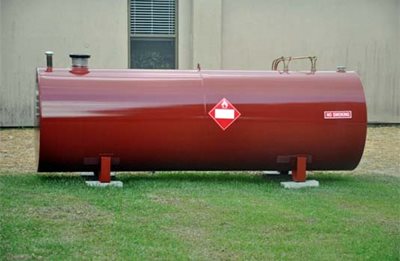
The fuel tank usually has sufficient capacity to keep the generator operational for 6 to 8 hours on an average. In the case of small generator units, the fuel tank is a part of the generator’s skid base or is mounted on top of the generator frame. For commercial applications, it may be necessary to erect and install an external fuel tank. All such installations are subject to the approval of the City Planning Division. Click the following link for further details regarding fuel tanks for generators.
Common features of the fuel system include the following:
(a) Pipe connection from fuel tank to engine – The supply line directs fuel from the tank to the engine and the return line directs fuel from the engine to the tank.
(b) Ventilation pipe for fuel tank – The fuel tank has a ventilation pipe to prevent the build-up of pressure or vacuum during refilling and drainage of the tank. When you refill the fuel tank, ensure metal-to-metal contact between the filler nozzle and the fuel tank to avoid sparks.
(c) Overflow connection from fuel tank to the drain pipe – This is required so that any overflow during refilling of the tank does not cause spillage of the liquid on the generator set.
(d) Fuel pump – This transfers fuel from the main storage tank to the day tank. The fuel pump is typically electrically operated.
(e) Fuel Water Separator / Fuel Filter – This separates water and foreign matter from the liquid fuel to protect other components of the generator from corrosion and contamination.
(f) Fuel Injector – This atomizes the liquid fuel and sprays the required amount of fuel into the combustion chamber of the engine.
Voltage Regulator
As the name implies, this component regulates the output voltage of the generator. The mechanism is described below against each component that plays a part in the cyclical process of voltage regulation.
(1) Voltage Regulator: Conversion of AC Voltage to DC Current – The voltage regulator takes up a small portion of the generator’s output of AC voltage and converts it into DC current. The voltage regulator then feeds this DC current to a set of secondary windings in the stator, known as exciter windings.
(2) Exciter Windings: Conversion of DC Current to AC Current – The exciter windings now function similar to the primary stator windings and generate a small AC current. The exciter windings are connected to units known as rotating rectifiers.
(3) Rotating Rectifiers: Conversion of AC Current to DC Current – These rectify the AC current generated by the exciter windings and convert it to DC current. This DC current is fed to the rotor / armature to create an electromagnetic field in addition to the rotating magnetic field of the rotor / armature.
(4) Rotor / Armature: Conversion of DC Current to AC Voltage – The rotor / armature now induces a larger AC voltage across the windings of the stator, which the generator now produces as a larger output AC voltage.
This cycle continues till the generator begins to produce output voltage equivalent to its full operating capacity. As the output of the generator increases, the voltage regulator produces less DC current. Once the generator reaches full operating capacity, the voltage regulator attains a state of equilibrium and produces just enough DC current to maintain the generator’s output at full operating level.
When you add a load to a generator, its output voltage dips a little. This prompts the voltage regulator into action and the above cycle begins. The cycle continues till the generator output ramps up to its original full operating capacity.
 Cooling & Exhaust System Cooling & Exhaust System
(a) Cooling System
Continuous usage of the generator causes its various components to get heated up. It is essential to have a cooling and ventilation system to withdraw heat produced in the process.
Raw/fresh water is sometimes used as a coolant for generators, but these are mostly limited to specific situations like small generators in city applications or very large units over 2250 kW and above. Hydrogen is sometimes used as a coolant for the stator windings of large generator units since it is more efficient at absorbing heat than other coolants. Hydrogen removes heat from the generator and transfers it through a heat exchanger into a secondary cooling circuit that contains de-mineralized water as a coolant. This is why very large generators and small power plants often have large cooling towers next to them. For all other common applications, both residential and industrial, a standard radiator and fan is mounted on the generator and works as the primary cooling system.
It is essential to check the coolant levels of the generator on a daily basis. The cooling system and raw water pump should be flushed after every 600 hours and the heat exchanger should be cleaned after every 2,400 hours of generator operation. The generator should be placed in an open and ventilated area that has adequate supply of fresh air. The National Electric Code (NEC) mandates that a minimum space of 3 feet should be allowed on all sides of the generator to ensure free flow of cooling air.
(b) Exhaust System
Exhaust fumes emitted by a generator are just like exhaust from any other diesel or gasonline engine and contain highly toxic chemicals that need to be properly managed. Hence, it is essential to install an adequate exhaust system to dispose of the exhaust gases. This point can not be emphasized enough as carbon monoxide poisoning remains one of the most common causes for death in post hurricane affected areas because people tend to not even think about it until it’s too late.
Exhaust pipes are usually made of cast iron, wrought iron, or steel. These need to be freestanding and should not be supported by the engine of the generator. Exhaust pipes are usually attached to the engine using flexible connectors to minimize vibrations and prevent damage to the generator’s exhaust system. The exhaust pipe terminates outdoors and leads away from doors, windows and other openings to the house or building. You must ensure that the exhaust system of your generator is not connected to that of any other equipment. You should also consult the local city ordinances to determine whether your generator operation will need to obtain an approval from the local authorities to ensure you are conforming to local laws a protect against fines and other penalties.
Lubricating System
Since the generator comprises moving parts in its engine, it requires lubrication to ensure durability and smooth operations for a long period of time. The generator’s engine is lubricated by oil stored in a pump. You should check the level of lubricating oil every 8 hours of generator operation. You should also check for any leakages of lubricant and change the lubricating oil every 500 hours of generator operation.
Battery Charger
The steart function of a generator is battery-operated. The battery charger keeps the generator battery charged by supplying it with a precise ‘float’ voltage. If the float voltage is very low, the battery will remain undercharged. If the float voltage is very high, it will shorten the life of the battery. Battery chargers are usually made of stainless steel to prevent corrosion. They are also fully automatic and do not require any adjustments to be made or any settings to be changed. The DC output voltage of the battery charger is set at 2.33 Volts per cell, which is the precise float voltage for lead acid batteries. The battery charger has an isolated DC voltage output that does interfere with the normal functioning of the generator.
a60e.jpg) Control Panel Control Panel
This is the user interface of the generator and contains provisions for electrical outlets and controls. The following article provides further details regarding the generator control panel. Different manufacturers have varied features to offer in the control panels of their units. Some of these are mentioned below.
(a) Electric start and shut-down – Auto start control panels automatically start your generator during a power outage, monitor the generator while in operation, and automatically shut down the unit when no longer required.
(b) Engine gauges – Different gauges indicate important parameters such as oil pressure, temperature of coolant, battery voltage, engine rotation speed, and duration of operation. Constant measurement and monitoring of these parameters enables built-in shut down of the generator when any of these cross their respective threshold levels.
(c) Generator gauges – The control panel also has meters for the measurement of output current and voltage, and operating frequency.
(d) Other controls – Phase selector switch, frequency switch, and engine control switch (manual mode, auto mode) among others.
Main Assembly/Frame
All generators, portable or stationary, have customized housings that provide a structural base support. The frame also allows for the generated to be earthed for safety.
|