Deciding Factors

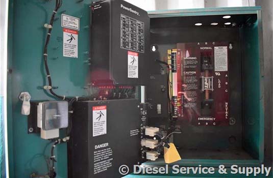
There are a number of different factors to consider when selecting an automatic transfer switch for a diesel generator, the most important being size. Part one of this article will discuss the type of load, voltage rating and continuous current rating.
Careful selection of an automatic transfer switch is important to ensure maximum reliability and adequate capability under both normal and emergency situations. However, in the end, the most common influencing factors are price and reliability.
Different Types of Loads
Underwriters Laboratory is the prevailing authority figure when it comes to independent testing of electrical products. Underwriters Laboratory or UL classifies automatic transfer switch loads under guideline UL 1008. The loads listed are Total System Loads, Motor Load, Electric Discharge Lamp Loads, Restrictive Loads, and Incandescent Lamp Loads.
Underwriters Laboratory requires that all transfer switches for diesel generators be clearly marked to specify what type of load it is capable of handling. The “Total System Loads” panel indicates that the switch can be used for a variety of loads described in the previous paragraph. However, when dealing with an incandescent (tungsten-based filament) load the total load should never exceed 30% unless the transfer switch is specifically rated to transfer a higher percentage of power to incandescent lamps.
In general, most transfer switches for used generators are rated to handle Total System Loads. It is always best to check the markings as some Total System Loads are marked “Resistance Only, Tungsten Only etc.” The overall project management hassle is greatly reduced for engineers by choosing a Total System Load from the onset of the project.
Voltage Ratings
Automatic transfer switches for used generators are unique in regards to, their electrical distribution system in that they are one of only a few electrical devices that are designed to have two unsynchronized power sources connected to it. For example, this could mean that voltages impressed on one side of the insulation, in the unit, may actually be as high as 960 volts on a 480-volt AC system. A well designed UL transfer switch will provide adequate spacing and insulation to cope with the increased voltage stress.
It is due to this reason of increased stress on the unit that spacing in transfer switches should be less than those shown in Table 22.1 in UL 1008, regardless of the component used as part of the transfer switch.
The voltage ratings for AC systems are typically 120, 208, 240, 480, 600 volts, single or polyphase. Standard frequencies are 50 or 60 hertz. Automatic transfer switches can be used for other voltages and frequencies if required, this also includes DC.
Continuous Current Rating
The standard expectation of an automatic transfer switch in regard to a continuous load is that the switch should be able to hold maximum value for three hours or more. Transfer switches differ widely from other emergency equipment in that they must continuously carry the current to critical loads, either from the normal source of power or emergency source. Whereas, a standby engine generator set usually supplies power only during emergency periods.
Automatic transfer switches for diesel generators are manufactured to meet continuous current ratings of 30-4000 amperes. Typically, the most commonly used ampere ratings include 30, 40, 70, 80, 100, 150, 225, 260, 400, 600, 800, 1000, 1200, 1600, 2000, 3000 and 4000 amperes.
Modern transfer switch technology is capable of carrying 100% of the rated current at an ambient temperature of 40° C. Transfer switches incorporating integral over current protective devices may be limited-to a continuous load current no more than 80% of the switch rating. In modern switches there are control measures in place to make sure no more than 80% of the load is continuous. However, in older units, system failure is a possibility for exceeding 80%.
Project engineers should anticipate future load requirements during the planning process. Not all projects require forethought into future load requirements however it is generally advisable to select a transfer switch with a continuous current rating equal to the total of the anticipated load.
To calculate the continuous rating for a transfer switch one must total the amperes required for all loads. To determine the load current for tungsten (incandescent) lamps and electric heaters one must total the wattage value. Mercury vapor, fluorescent vapor and sodium vapor lamp load currents must be based on the current that each ballast or autotransformer draws, not on the total watts of the lamps. Motor full load currents only determine motor loads and are not an accurate measure for other types of loads. Locked rotor and motor inrush currents do not need to be considered in sizing a transfer switch that is UL listed for the Total System Load. In most cases, there is no need to de-rate a transfer switch for use in ambient temperatures up to 40° C; this includes switches that are installed in the switchboard or in a separate enclosure.
Example Formula for Finding Ampere Rating
The following example involves needing to find the ampere rating for a total system load:
Requested: An automatic transfer switch rated for Total System Loads, for a 208/120 volt, three phase, four wire circuit consisting of the following three phase balance load:
115 kW heating load
I = 115 kW/208V x 3 = 320 amps
64 kW tungsten lighting load
I = 64 kW/208V x 3 = 178 amps
Three 10 HP motors, @ 32 amps each
I = 3 x 32 = 96 amps
Total Load = 320 + 178 + 96 = 594 amps
When reviewing the tungsten load take note that since the load does not exceed 30% of the total load, select a three-pole transfer switch rated at least 600 amperes. Typical diesel generator line currents versus kW ratings can be found in UL 1008. For the previous example a 200-kW generator may be suitable for the application, provided it can handle the inrush currents.
Proper sizing of a transfer switch for a diesel generator requires careful consideration of the load type, voltage at the point of application and continuous load current. In the next article I will continue the discussion with overload and fault current ratings, protective devices ahead of the transfer switch, UL long-time ratings and other special considerations. As always, it is best to consult a professional electrical engineer before embarking on any sort of power generation project.
Referenced: Daugherty, Herbert. 'Automatic Transfer Switches' p. 207-209 On-Site Power Generation 4th Edition. Boca Raton, Florida: Electrical Generating Systems Association, 2006.
>>Back to Articles & Info<<